

In the humming server rooms and above the drop ceilings of modern facilities lies a hidden vulnerability one that standard network diagnostics routinely overlook.
In the humming server rooms and above the drop ceilings of modern facilities lies a hidden vulnerability one that standard network diagnostics routinely overlook. Many organizations operate under a dangerous assumption: if link lights are green and ping tests pass, their wired infrastructure must be healthy. But beneath these indicators often lurk issues that threaten performance, compliance, and safety.
A recent 16,000 sq ft wired site survey at a major U.S. distribution center shattered this myth, uncovering systemic cabling problems that left unresolved could have led to considerable annual downtime. This wasn't just about a faulty cable or an overburdened switch. It was an exposé of how widespread complacency around structured cabling standards creates ticking time bombs in enterprise environments.
Key findings included:
- Performance bottlenecks, with degraded throughput despite "10Gbps-capable" hardware
- Compliance violations, including TIA-568.2-D and NEC 300.11 lapses
- Safety hazards, such as overheated PoE++ runs and unterminated cable shielding
What appeared to be a stable network was, in reality, being quietly throttled by signal degradation, cable fatigue, and improper distance planning. This project wasn't just about replacing wire it was about designing a future-proof installation strategy grounded in high-resolution survey data.
The result? A resilient, high-performance physical infrastructure built to support long-term growth, operational reliability, and true compliance. If your facility relies solely on software indicators to measure network health, it may be time to take a closer look at the physical layer before small oversights become expensive failures.
Key Installation Objectives
- Upgrade outdated copper cabling with shielded CAT6A to support APs and edge devices
- Introduce a new IDF to resolve excessive cable lengths
- Use fiber backbone to bridge MDF to IDF across warehouse wings
- Deploy a number of APs for full indoor/outdoor coverage with external antennas in high-rack zones
- Mount hardware to meet environmental and access constraints (e.g., 30' ceilings)
- Ensure all cabling and AP placements comply with standards to support 10Gbps uplinks and optimal Wi-Fi performance.
Structured Cabling: Replacing the Network's Support
A network is only as strong as its physical layer. The existing infrastructure in this facility included legacy copper cabling and ad-hoc pathways that had evolved with the space, but not with its technology needs. The new approach focused on predictability, labeling, and long-term maintenance.
Horizontal Cabling Strategy:
- New CAT6A cables were installed to support APs and edge devices
- Previously installed cables were reused after thorough inspection for shielding and continuity
- Cables were routed with careful attention to bend radius, separation from power lines, and ceiling space congestion
Routing & Mounting:
- Cable trays and J-hooks were installed to provide permanent cable pathways
- In some areas, existing penetrations were fire-sealed and reused; in others, new grommets and sleeves were installed for code compliance
- Cable slack loops were introduced at endpoints to simplify future changes
Labeling & Documentation:
- Cables were labeled at both ends, tagged with drop numbers, length records, and floor plan references
- All labeling followed TIA-606 standards and was recorded in an installation matrix handed over to the client
- Patch panels were color-coded based on destination zone (e.g., docks, offices, racking)
MDF/IDF Buildout: A Backbone Reinforced
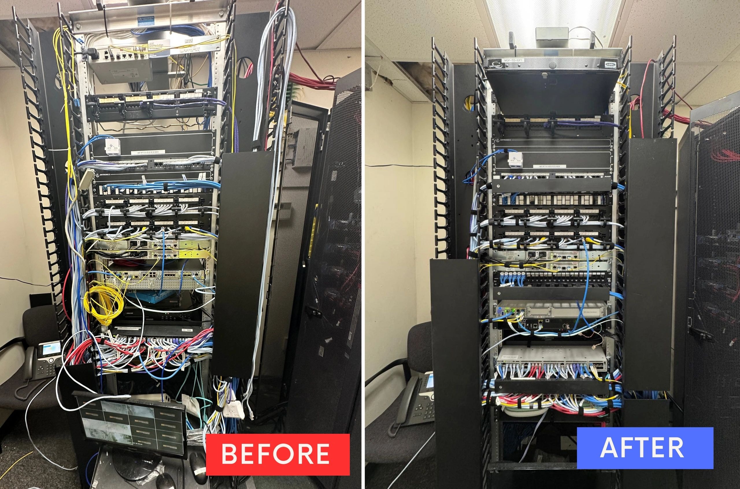
MDF Room Upgrades:
- Redundant switch stacks were reorganized to distribute AP loads evenly across PoE+ ports
- Patch panels were consolidated, freeing up 6U of rack space
- A UPS unit was added and the existing PDU reorganized to prevent brownouts
- All open copper and fiber ports were labeled, dressed, and documented
IDF Deployment:
- A new IDF cabinet was mounted near the shipping dock to reduce cable distances to far-end APs
- Single-mode fiber was pulled through conduit over a 350-foot span
- Slimline rack was grounded to a new busbar with insulated bonding braid
- Dual fiber links were terminated to support redundancy and failover paths
Wireless AP Installation: Ceiling to Steel Truss
Office Zones (1st and 2nd Floor):
- APs installed flush with acoustic tiles to preserve aesthetics
- Internal antennas provided clean coverage in meeting rooms and corridors
- Mounted at 8 feet, connected to shielded Cat6A for PoE+ delivery
Warehouse Zones:
- APs mounted on I-beams at 20–25 feet, ensuring vertical and horizontal coverage in high-bay racking aisles
- Patch and omni-directional antennas selected based on propagation patterns validated in the site survey
- Cable runs were kept under 295 feet with new IDF acting as mid-span link
Loading Dock:
- External antennas mounted just inside the building envelope to minimise weather exposure
- Mounts reinforced to withstand air pressure changes and vibrations from freight movement
- Antenna alignment was verified using handheld directional testers post-mount
Testing and Post-Install Validation
Once physical installation was complete, a multi-layered testing phase began:
Copper Testing:
- Every new CAT6A cable was tested using a certified cable analyser
- Tests included length, wire map, NEXT, PSNEXT, ACR-F, and Return Loss
- All links passed at 10GBase-T with margin, and reports were handed off in digital format
Fiber Validation:
- OTDR testing confirmed signal integrity across the 350-foot backbone
- Insertion loss and reflectance were within limits for SM fiber
- LC connectors were polished and cleaned before final patching
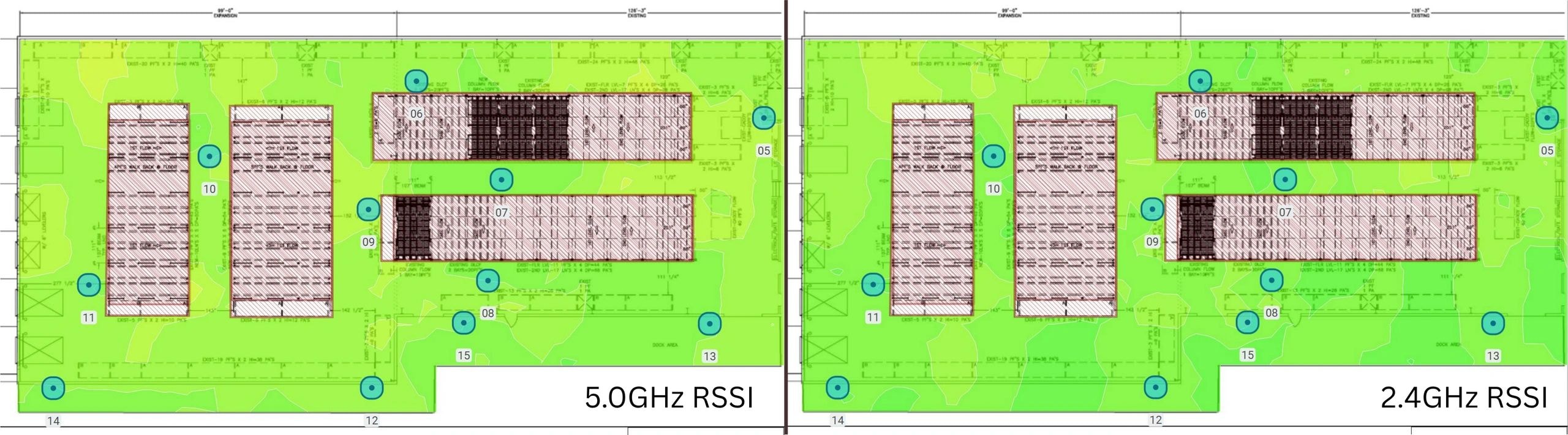
Wireless Heatmap Validation:
- A post-install wireless survey was conducted to validate AP placement
- Overlap exceeded 20% across all critical areas
- Roaming was tested using tablets and handheld scanners
- No coverage dead zones were identified, and signal strength averaged above -62 dBm
Installation Challenges & Resolutions
Long Distance Limitations:
- APs originally routed to MDF would have exceeded 300 feet
- A new IDF cabinet was installed at a midway point, reducing length to within spec
Cable Reuse Evaluation:
- Existing cables were originally marked for reuse and were retested
- Time-domain reflectometry revealed minor shield degradation in one replaced proactively
Environmental Considerations:
- Several APs near the loading dock had to be secured against vibration and dust
- Industrial Velcro and custom-mount hardware were introduced to address the issue
Final Results
The results of this upgrade were both quantitative and qualitative:
- Latency on handheld devices dropped from 120 ms to under 3 ms
- Signal loss from edge APs dropped by 20–25 dB after switching from legacy runs
- Client staff reported zero roaming interruptions during real-time pick-pack operations
- UPS-backed infrastructure ensured uptime during a simulated power drop test
Lessons from the Field
- Do not rely on ping tests to assess cable health certify everything
- Leave extra rack space and spare ports it's never wasted
- Drop ceilings make AP install easy but verify tile load ratings before mounting
- Label in the field, not just in the plan field accuracy saves hours later
Upgrading your facility's network is more than a switch swap. It's a physical transformation that affects every device, every team member, and every digital process. If your systems feel slower than they should or you haven't audited your cabling in over 5 years it may be time.
Contact our commercial deployment team for a no-pressure consultation. We'll help you build a network that performs as reliably as your business demands at sales@3sab.ca or through our website https://3sab.ca/